Electric Cylinder Design Considerations
Load Capacity
All anticipated loads should be within the rated capacity of the cylinder. Loads on the cylinder in most applications include static loads, dynamic or moving loads, cutting forces or other reaction forces and acceleration/deceleration loads.
For shock loads, the peak load must not exceed the rated capacity of the cylinder, and an appropriate design factor should be applied commensurate with the severity of the shock.
For accidental overloads not anticipated in the design of the system, cylinders can sustain without damage the following overload conditions: 10% for dynamic loads, 30% for static loads.
For multiple cylinder systems, load distribution should be considered. System stiffness, center of gravity, drive shaft windup and lead variation in the lift shafts may result in unequal load distribution.
Horsepower Ratings
Standard DD and RAD Electric Cylinder Models are supplied with electric brake-motors sized for the load and speed rating of the cylinder.
The allowable duty cycles for DD and RAD worm gear cylinders being used at full rated load are:
- Ball Screw Cylinders = 35%
- Acme Screw Cylinders = 35%
If an Electric Cylinder is applied at less than rated capacity, higher duty cycles may be possible. The best way to determine allowable duty cycle is to measure the cylinder gear housing temperature. The temperature of the housing near the worm must not exceed 200°F.
For Electric Cylinders supplied without brakemotors, use the information in the "Electric Cylinder Design Data" chart for motor sizing. The horsepower is calculated by using the following formula:
| Horsepower per cylinder = | Torque to raise 1 pound × Number of pounds to be raised × Input rpm |
| 63,025 |
The "Torque to raise one pound" value is particular to each cylinder and can be obtained from the "Electric Cylinder Design Data" charts on pages 20, 34-35, and 54-55.
Maximum horsepower ratings are based on intermittent operation. To determine whether performance is within horsepower and duty cycle limits, measure the cylinder temperature. The temperature of the housing near the worm (or at the thrust bearing mounting block for ILA cylinders) must not exceed 200°F.
CAUTION: Do not exceed the maximum allowable input horsepower for a cylinder.
Column Strength
Electric Cylinder capacity may be limited by its column strength. Column strength is the ability of the cylinder to hold compressive loads without buckling. With longer screw lengths, column strength can be substantially lower than nominal cylinder capacity. When the lift screw is in tension only, travel is limited by available screw and/or tube material or by screw critical speed. If there is any possibility for the cylinder to go into compression, the application should be checked for sufficient column strength. The charts on each cylinder specification page are used to determine the cylinder size in applications where the lift screw is loaded in compression.
The charts assume proper cylinder alignment with no bending loads present. Effects from side loading are not included in this chart. Also, cylinders operating horizontally with long lift screws can have significant bending from the weight of the screw and tubes. Consult Nook Industries if side loads are anticipated.
Cylinder Sizing Data
Cylinders are limited by two constraints: load capacity and horsepower. The load capacity of the cylinder is limited by the physical constraints of its components (drive sleeve, lift shaft, bearings, etc.). The horsepower limit of the cylinder is a result of the ability to dissipate the heat generated from the inefficiencies of its components.
In order to test for these constraints, application information must be collected. The data required to size a cylinder includes:
1) Total Load - The total load includes static loads, dynamic loads and inertia loads from acceleration and deceleration. Also consider reaction forces received from the load such as drilling or cutting forces when using a cylinder to move a machine tool.
2) Number of Cylinders - The number of cylinders used depends on physical size and design of the equipment. Stiffness of the equipment structure and guide system will determine the appropriate number of cylinders required. Fewer cylinders are easier to drive, align and synchronize. For multiple-cylinder arrangements, do not assume equal loading. Calculations should be based upon “worst case” unequal loading.
3) Travel Rate - Establishing a travel rate allows for a quick cylinder selection and will be used to evaluate critical speed and horsepower limits. The desired rate should include time for acceleration/deceleration.
Travel - Travel is the total distance the cylinder extends. This is the number that is used to calculate maximum compressive load. For cylinders with nonstandard retracted lengths, include the additional length in the compressive load evaluation.
5) Duty Cycle - The duty cycle is the ratio of run time to the total cycle time.
6) Type of Guidance - Every linear motion system needs something to move the load and something to guide the load. The degree of guidance (stiffness, accuracy, etc.) is based on application requirements.
Cylinder Selection
Once the cylinder sizing information is collected, a preliminary cylinder selection can be made and verified.
1) Select a Standard Cylinder - Use the DD, RAD, and ILA Design Data and Quick Reference Charts on pages 20, 34-36, and 54-56 to find a unit which matches the desired force and speed. Choose between a ball screw or acme screw model based on duty cycle (model suffixes which begin with “A” are acme models).
2) Travel Length - When a unit is chosen, go to the product specification page for that model. Check that the desired travel length does not exceed column strength and maximum travel limits. A larger capacity cylinder may be required in order to stay within these limits.
NOTE: Travel length must include any over-travel to accommodate stopping distance.
3) Reference Number - Use the information on page 21, 37, or 57 to specify a complete Electric Cylinder Reference Number.
If the cylinder is to be used with a motor other than those listed in the catalog, if multiple cylinders are used or if the cylinder is manually operated, go to the Electric Cylinder Design Data on pages 20, 34-35, and 54-55.
1) Select a Cylinder - Choose a model whose basic capacity matches or exceeds the expected load. Make certain the dynamic and static loads do not exceed the cylinder capacity. In multiple cylinder applications, check the distribution of the load for potential uneven loading on the cylinders.
2) Speed - Use the "turns for one inch of travel" from the chart to determine the input speed required. If travel rate and motor speed are known, divide the motor speed (rpm) by the travel rate (inches per minute) to determine the "turns for one inch of travel."
3) Motor Horsepower - Calculate the horsepower required from the load, speed and “torque to raise one pound value” from the chart. Use the horsepower calculation on page 12.
If using the cylinders in multiple cylinder systems, check the total horsepower. Remember that additional gearboxes and couplings used to distribute power to the cylinders are not 100% efficient. If the horsepower required exceeds the maximum value for the cylinder selected, several solutions are possible.
- Use a larger cylinder model to increase the maximum allowable horsepower
- Use a Ball Screw Cylinder to reduce the power required to do the same work
- Operate at a lower input speed
- Use a RAD cylinder to bring the power requirement within acceptable limits
Upon selecting a motor and brake, verify that the brake has sufficient torque to both hold the load and stop the load.
CAUTION: Cylinders with high lead ball screws (HL and SL) may require larger brakes to stop the load. An appropriately sized brake will insure against excessive "drift".
4) Column Strength - If it is possible for the cylinder to be loaded in compression, check for column strength. Consider cases where a unit normally loaded in tension can be compressively loaded if it runs into an obstruction. Also check horizontal applications for compressive loading due to acceleration or deceleration.
5) Cycle Time - If using a worm gear style Electric Cylinder, make sure cycle time does not exceed the allowable duty cycles.
6) Life - For Ball Screw Cylinders, check life expectancy against the life charts.
7) Reference Number - Use the information on page 21, 37, or 57 to specify a complete Electric Cylinder Reference Number.
Installation
The alignment of the cylinders directly affects their service life. Cylinders must be properly aligned in all planes so the actuator tube can move in and out without evidence of binding.
Since the majority of cylinder applications use the cylinders with clevis or trunnion mounts, simply align the clevises and install the cylinder.
Set limit switches before operating. Allow for drift when setting the position. The actuator tube can move (rotate) until the unit is installed. Turn the actuator tube in or out to get the cylinder to a known position before installation to prevent over-travel.
Maintenance
Electric Cylinders require minimum maintenance. In addition to maintaining lubrication levels in the gearbox and tubes, the following items should be checked:
- The actuator tube should be kept free of dirt. If possible, the actuator should be returned to the retracted position when not in use.
- For acme cylinders, lash between the lift shaft and travel nut greater than 1/4 the screw pitch indicates the need for replacement of the cylinder lift shaft components.
- For machine screw or ball screw worm gear Electric Cylinders, check for excessive backlash between the worm and worm gear. Lash in excess of 30° for ratios 5:1 to 8:1 and 60° for ratios 20:1 and 24:1 indicates the need to replace the worm and worm gear.
Lubrication
Electric Cylinders require lubrication to operate efficiently and with maximum life. Standard lubrication is NLGI #2 grease. If operating conditions exceed -20°F to 200°F, contact Nook Industries, for alternative lubricants.
The cylinder gear boxes are shipped pre-greased unless otherwise specified. Before operating any unit, check the lubricant level. All cylinder housings are furnished with a grease fitting. Most have a pipe plug opposite the grease fitting. When adding grease to the housing, remove the pipe plug and fill the unit until grease exits the pipe plug opening. Overfilling the cylinder may result in grease leakage from the seals.
In normal operation, cylinder lubricant levels should be checked once per month. Application conditions may dictate a more or less frequent lubrication cycle. In extreme conditions, automatic lubrication may be desired.
Lubricants containing additives such as molydisulfide or graphite should not be used.
The lift shafts (ball and acme screws) inside the Electric Cylinder actuator tube receive lubrication through the fittings on the outside of the housing tube. Lubrication added to the housing tube can pass to the screw regardless of actuator tube position. The best way to lubricate this section of the cylinder is to add some lubricant when the cylinder is fully retracted and additional lubricant when the cylinder is extended beyond where the guide is past the lube port (see cylinder cutaway views on pages 19, 33, and 53).
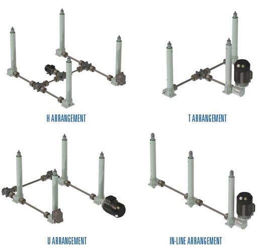
Arrangements