
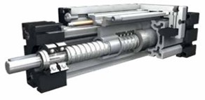
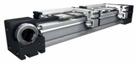
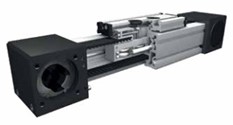
Screw Driven Modular Linear Actuators
Outstanding positioning and repeat accuracy with higher speed forces.
Screw Driven Modular Linear Actuators use the finest acme and ball screws manufactured in the world. They allow for direct in-line motor mount with or without an in-line or parallel gear box. They are an established as a popular standard in precision applications such as processing machines and machine tools.
- High thrust /torque/stiffness
- Up to 3 M screw length
Features
- Excellent positioning/repeat accuracy
- Long service life/operational reliability
- High drive stiffness/High thrust forces
- Smooth and quiet motion
- Low breakaway/drive torque
- High efficiency with the ball screw drive
Acme Screw or Ball Screw Drive
- Ball Screw = 0.025 mm repeatability
- Ball Screw = high efficiency/accuracy
Acme screw drives are suitable for transferring large axial forces and also offer the advantage of self-locking. Our linear axes with thread drives are long established as a popular standard in robust and precise applications in the field of processing machines and machine tools.
- ACME Screw = 0.2 mm repeatability
- ACME Screw = standard accuracy, minimum wear
Modular Actuator Product Selector
Easily design your own linear actuator system based on your unique application with the DESIGN GUIDE PRO tool. Enter your parameters to determine the best product fit.
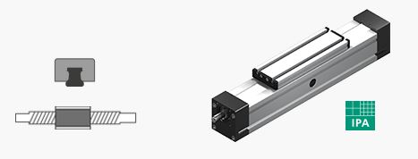
V Groove Guided
The carriage moves along the unit guided by V-slides that are adjustable to reduce lash. The linear opening of the unit is sealed with a stainless steel cover plate to make the unit splash-proof and dust-tight.
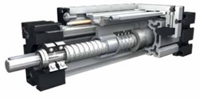
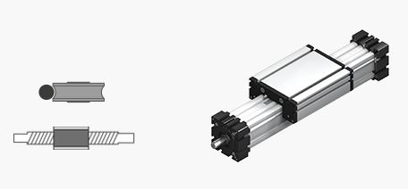
Internal Roller Bearing Guided
The carriage moves along the unit guided by hardened steel guide rods on the inside of the actuator that are adjustable to reduce lash. The linear opening of the unit is sealed with a stainless steel cover band to make the unit splash-proof and dust-tight.
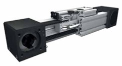
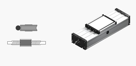
External Roller Bearing Guided
The carriage moves along the unit guided by hardened steel guide rods on the outside of the actuator that are adjustable to reduce lash. The linear opening of the unit is sealed with a stainless steel cover band to make the unit splash-proof and dust-tight.
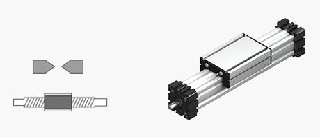
Internal Profile Rail Guided
The carriage moves along the unit guided by a single or dual internal profile rail on the outside of the actuator that are adjustable to reduce lash. The linear opening of the unit is sealed with a stainless steel cover band to make the unit splash-proof and dust-tight.
External Roller Bearing Guided
ELT/ELK 30, 40, 60, 60S, 80, 80S, 100, 125
An aluminum hollow section with integral, parallel ground and hardened steel guide rods. The carriage has play-adjustable ball-bearing rollers which engage with the guide rods. The rotating screw causes linear motion of the ball nut, which is connected to the carriage. The slot necessary for this is covered by a stainless steel strip, making the unit dust- and splash-proof. Lateral adjustment of movement for parallel units (or when two carriages are mounted on one unit) is provided by the ball nut mounting.
- Fitting position: As required, max. length 3,000 mm
- Carriage mounting: T-slots and tapped holes
- Unit mounting: T-slots and tapped holes in the mounting surfaces.


Internal Roller Bearing Guided
DLT/DLK 120, 160, 200
A rectangular aluminum profile with 2 integrated roller guides. The carriage is driven by means of a rotating spindle with leading nut. Where two parallel linear units are used (or where two carriages are mounted on one unit) the leading-nut receiver can be used to adjust the symmetry of the carriages. The openings of the guide body are sealed with 3 stainless steel cover bands to protect the drive from splash water and dust.
- Fitting position: As required. Max. length 3,000 mm without joints.
Carriage mounting: T-slots. - Unit mounting: T-slots and mounting sets. The linear axis can be combined with any T-slot profile.
- Carriage support: In the standard version, the carriage runs on 8 rollers which can be adjusted and serviced at a central servicing position. For longer carriages, the number of rollers can be increased. Repeatability ball screw ± 0.025 mm, trapezoidal thread
± 0.2 mm.
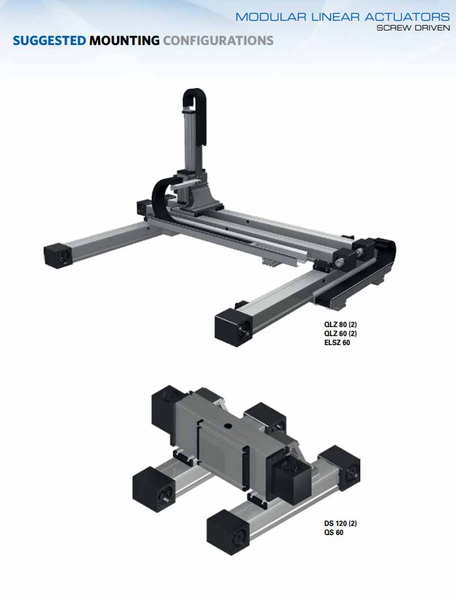
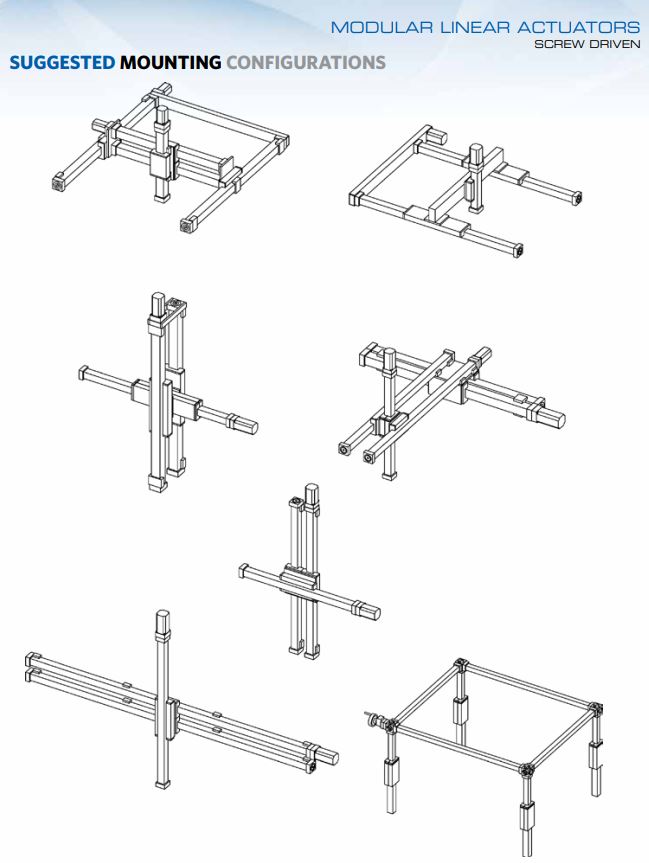
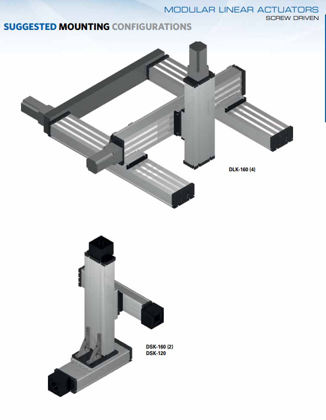 Mounting Configurations


Internal Profile Rail Guided
QST/K 60, 80, 100
A square aluminum profile with an integrated ball rail. The carriage is driven by means of a rotating screw with leading nut. The openings of the guide body are sealed by a stainless steel cover band to protect the drive from splash water and dust.
QST/K
- Fitting position: As required, max. length 3000mm
- Carriage connection: T-slots
- Unit mounting: Half round slots and tapped holes in the bearing blocks, mounting sets
QST/KE
- Carriage connection: T-nuts and bores through the cover.
- Unit mounting: Bearing blocks
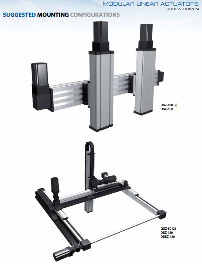
 Mounting Configurations


DST/K 120, 160, 200

A rectangular aluminium profile with 2 integrated rail guides. The carriage is driven by means of a rotating screw with leading nut. Where two parallel linear units are used or where two carriages are mounted on one unit, the leading-nut receiver can be used to adjust the symmetry of the carriages. The openings of the guide body are sealed with 3 stainless steel cover bands to protect the drive from splash water and dust.
- Fitting position: As required. Max. length 3,000 mm without joints.
- Carriage mounting: By T-slots.
- Unit mounting: By T-slots and mounting sets. The linear axis can be combined with any T-slot profile.
- Carriage support: In the standard version, the carriage runs on 4 runner blocks which can be serviced at a central servicing position. For longer carriages the number of runner blocks can be increased.
- Repeatability: Ballscrew ± 0.025 mm, trapezoidal thread ± 0.2 mm.


V Groove Guided
EGT/EGK 30, 40, 60, 80
An aluminum square profile with lateral V-guides. The carriage (screw driven) moves along the unit guided by adjustable V-slides free of play. Where two linear units are used in parallel (or two carriages are mounted on one unit), the leading-nut receiver can be used to adjust the symmetry of the carriages. The linear opening of the unit is sealed with a stainless steel cover band to make the unit splash-proof and dust-tight.
- Fitting position: As required. Max. length 3,000 mm
- Carriage mounting: T-slots, tapped holes (size 40)
- Unit mounting: T-slots or tapped holes in the bearing block, mounting sets.
 Mounting Configurations


Need Help Selecting Modular Linear Actuators?
Collaborate with one of our technical experts on the specifics of your application to ensure the ideal product fit that best meets your performance requirements and budget.